My New Arcade Cabinet
Well the pandemic largely killed any drive I had for table top miniature games, but it did provide me and more importantly one of my friends the opportunity to build something that I've wanted for decades now.


Modeled after a "Big Red" Neo Geo MVS Cabinet from the 90's


My youngest daughter enjoying Pac Man
Basically I had been talking about wanting to build an arcade cabinet nearly my entire adult life but when I saw the cost for buying a kit it was hard to justify spending the money on myself when we had other uses. Fortunately I have my friend Ray, who was looking for woodworking projects to do while we were all staying at home because of a global pandemic.
So about 6 months ago I bought two sheets of MDF and a half sheet of plywood, which was lucky for me given the current price of lumber. Ray, of course, has a pickup truck and we hauled it to his house and I helped with the initial cuts.

This is Ray. Ray is handy. Be like Ray.
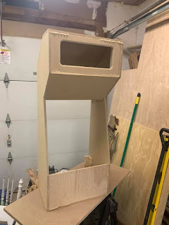
I did the initial design of the cabinet, with the plan of it being down in my living room and replacing a piece of shelf furniture we use to hold our movies + video game cases. Since we needed at least some shelf space to hold the video games for our current consoles, I decided the bottom part of the cabinet would be shelves rather than a big box. Of course now it lives upstairs in the game room since we'd prefer the kids not be in the living room with the adults when our friends visit.
After sending the initial Visio files to Ray, he started making modifications to allow the build to be more structurally sound: instead of the shelves going all the way back, they would be half-depth so the base of the cabinet would be like an I beam. He then pointed out that the cabinet was the right height for standing and using the control panel for an average adult, but the actual bartop portion was a little short - the lighted marquee would likely be shining in my eyes when I used the thing. So we ended up making things a bit taller for the top half of the system.
Design Choices
The overall design was built around my old Dell 2001FP monitor. I've literally had it since just before I got married, when my wife bought it for me as a birthday present to play Doom on - back in 2004. I wanted to use this since it was fairly big for a 4:3 monitor at 20.1 inches and it let me finally upgrade my secondary monitor on my gaming PC to a widescreen.
Unlike a lot of arcade cabinet kits you find these days I wanted a 4:3 monitor since that's the aspect ratio of nearly all the games I want to play on this. It also kept the width down so I could eventually put the cabinet in my living room once the kids get older.
Unlike a lot of arcade cabinet kits you find these days I wanted a 4:3 monitor since that's the aspect ratio of nearly all the games I want to play on this. It also kept the width down so I could eventually put the cabinet in my living room once the kids get older.
I also decided to make the control panel wide enough to let two adults stand side by side with space to spare. So the overall control panel will be 33" wide in total. We used half inch MDF for the "Bartop" portion of the cabinet and control panel, and then three quarter inch MDF for the base shelf and stand.


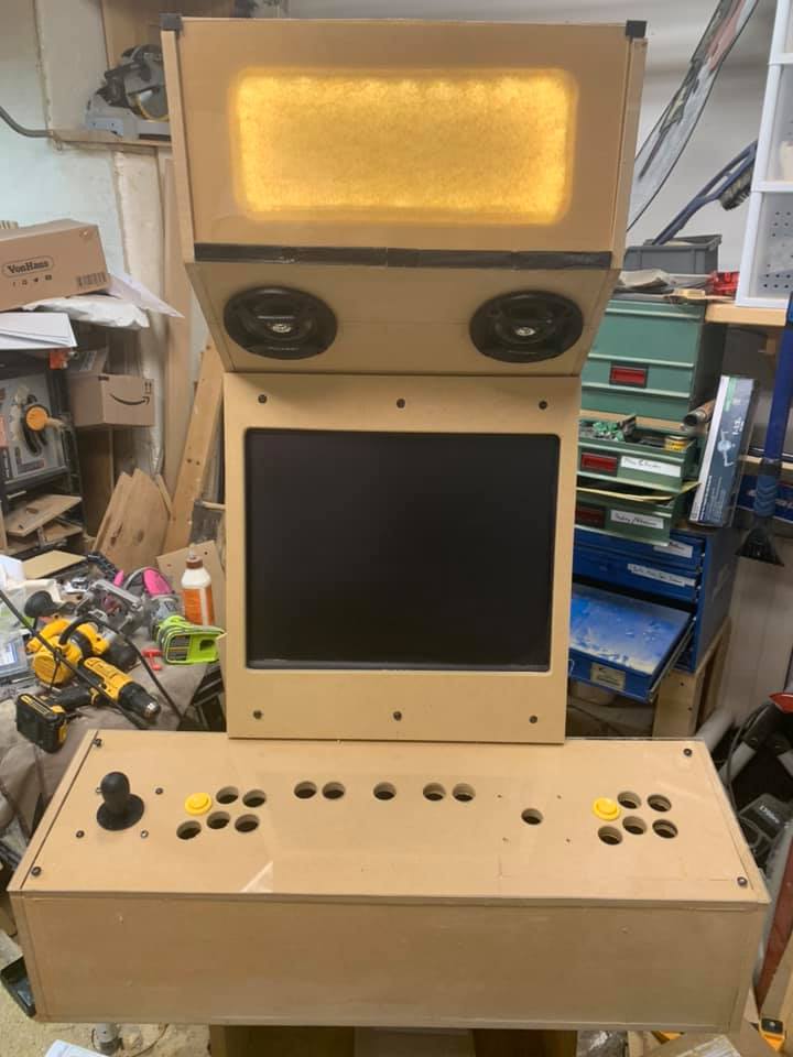
An important decision was the control panel layout. I was used to a more complicated 8 button layout that let you basically do anything from the classic US layout of a 4 button Neo Geo or the 6 button Capcom setup, I elected to go with the layout commonly found on Japanese Candy cabinets where it's only 6 buttons but things are angled so you can easily switch to using the 4 button Neo layout.
A few years ago I had re-done the internal electronics for these very old, but very high quality Pelican joysticks that I originally replaced the parts with Happ parts back in the early 2000's when it came out.
A few years ago I had re-done the internal electronics for these very old, but very high quality Pelican joysticks that I originally replaced the parts with Happ parts back in the early 2000's when it came out.

Since I have literally two other sets of custom joysticks I've built, I decided I was going to gut these bulky sticks and use the parts and electronics for the cabinet, saving some cash. I'll include the detailed electronics in the parts list.

Finally I decided on springing for a Raspberry Pi 4 so that I could have something powerful enough to emulate Dreamcast, where my old Pi 3B+ just didn't have the horsepower to do that. So now my friends and I can play Capcom vs. SNK 2, Street Fighter 3 Third Strike, Marvel vs. Capcom 2, and Ikaruga + other quasi-modern shmups that were meant for a 4:3 screen.
Electronics Selection
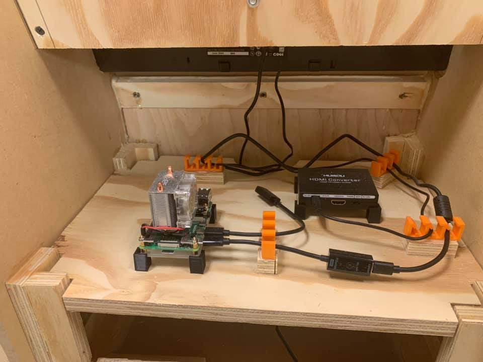
I have the cabinet running on a Raspberry Pi 4 B 8Gb single board computer using a Pi ICE Tower Cooler. I had to get a mini HDMI to HDMI converter cable and power supply, but those are pretty generic.
I went with a Musou HDMI Audio Extractor so that I could get a clean digital audio out rather than rely on the rather cheap analog audio electronics for the Pi's headphone jack output.
The HDMI video went to a HDMI to DVI cable, and the audio used the RCA outputs to a Kinter K3118 Texas Instruments amplifier. This drove a pair of Pioneer 4" Speakers.
I used some adjustable brightness white LED strips to backlight the marquee.
Ray ended up selecting some 1/4-20 x 1" button head socket cap screws for the external bolt bits to hold parts together (I may be including this link just for my own future reference if I need replacement bolts).
Power used a few different pieces: A ToToT 4 Positions Dual Row Terminal Strip, with a Besmelody Rocker Toggle Switch, and a Industrial Metal Power Strip with 10 outlets, mainly to accommodate various large power bricks for each of the components.
Finally for the control encoding I used two Reyann Zero Delay Arcade USB Encoders. I found they didn't work great in Windows for modern fighting games on Steam, but they did work well with emulators and perfectly with RetroPie.
Artwork and Painting
Even though it was a RetroPie cabinet, I wanted to style the cabinet after a Neo-Geo MVS "Big Red" cabinet since I was a big SNK fan back in the day. Ray recommended Valspar satin cabinet paint from Lowes and I just bought a quart of Black and Red that looked close enough.
I also spent some time using GIMP to re-create some classic Neo-Geo artwork for the control panel and the marquee.


Get ready to scroll because here comes the two build montage's one for Ray's fabrication and then for my final cleanup, paint, and electronics assembly.
Ray's Build Montage and Design Mods
I've gotten a lot of requests for pictures of everything being built along the way, and Ray was pretty meticulous about taking pics at various stages of the build. Before I get to the pics I wanted to talk about some mods Ray had to do in order to get things to fit. One problem he had was that we either mis-measured or blade width came into play on the cuts so that the monitor didn't quite go into the sides of the cabinet. Ray ended up having to take a router to the sides to take out part of the MDF so we could wedge the monitor in. It works great, though it was unexpected.
Another minor issue is that the speaker holes ended up conflicting with the internal plywood supports for the MDF, which means I'm basically using only 3 screws to secure the speakers, but that doesn't seem to be a problem.
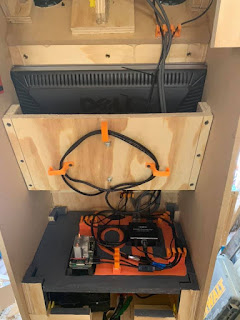
Then there's the design improvements made. Ray wanted to make the internals as much a work of art as the outside, he also got a new 3D printer in the middle of the build and I think he wanted to play with designing 3D printed parts to augment projects like this. He created cable holders and some keyed inserts to keep the back panel on. He also created mounts for the USB encoders, the Pi, and HDMI audio extractor.
He also created a new shelf so that the electronics could be separated from the power section and we decided on a small hole for the power switch on the side of the cabinet behind the extension of the 1P portion of the control panel for easy power on/off.
Volume control was going to be tricky since I just bought a basic amplifier, but I had the idea to mount it behind the marquee so if I had to adjust the volume I could just take the marquee off and adjust the volume knob.
Ultimately Ray's skill during fabrication pulled through and it came out flawlessly. Both Ray and I are engineers working in IT, the parallels to the design and implementation process we find in our professional lives was a good source of amusement along the way.


My Final Assembly, Paint, and Control Panel Work
At this point the scariest part that was left for me was to not screw up the paint job and to properly get the control panel artwork mounted to the wood part of the CP and then the plexiglass aligned perfectly on top of that without messing everything up.
Ray delivered the cabinet to me last Sunday. I basically stayed up till midnight on Monday doing disassembly, spackling woodworking dents/holes. I was up till midnight again Tuesday painting (2 coats for black and then 3-4 coats for the red. Then I was up till 2AM on Wednesday finishing the cabinet and doing the aforementioned control panel work.
One final problem I found was that the mounts Ray made for the USB encoders was at the bottom of the control panel assembly, and the leads for my electronics were not going to reach that way and be serviced. As such I was able to take them off the mount he glued them to and used some sticky Velcro to get it attached to the actual CP board itself.
There was also the weird issue of the marquee. Ray had 3D printed some tabs to hold the bottom and top-sides of the marquee in, though it was a little unseemly and I thought we were going to have to cut another piece of wood and find some way to secure it as a bezel around the marquee. That seemed like a hard job to graft a secure mounting system for it and then going back to Ray to do more wood work and I decided I could cosmetically fix it with some creative painting and then resizing the marquee to be just short enough to let the top half inch MDF show through.
Luckily I was able to find a local print shop that printed both pieces of artwork, in half an hour, and cut them to size, for a mere $10. Thanks ARC Document Services.


Comments
Post a Comment